How do I print to the laser from AutoCAD?
The following article includes general instructions and tips on printing to an Epilog Laser system from AutoCAD Software.
AutoCAD is a very powerful software tool that is often used in conjunction with the laser for cutting applications. Like any tool, understanding how it works and its limitations are helpful in getting the most out of it. AutoCAD versions 14 to the present are typically compatible with Epilog systems, though each version uses slightly different printing conventions that may or may not affect the way you print, and different versions may produce different output from the laser .
Printing & Plotting
Sending jobs from AutoCAD is heavily dependent on the print settings in the AutoCAD Print/Plot window. Since there are so many different settings that AutoCAD requires, it is important that you double-check all of the settings that are critical to success. Previewing your image before sending it to the laser is very helpful in preventing print problems.
AutoCAD is capable of producing extremely complicated drawings with many layers, colors, etc. Since there is no limit to the level of complexity that an AutoCAD drawing can achieve, users should keep in mind that the laser is a 2D cutting machine that usually cuts a single piece of material in any given job. While your laser system is capable of handling complex drawings, users may find that eliminating extraneous detail before “Printing/Plotting” may make their laser equipment more productive.
Color Mapping
Creating objects of different colors in AutoCAD allows the user to take advantage of the Vector Color Mapping capabilities of the Epilog Dashboard print driver. Color mapping assigns different Speed and Power settings to an object based on its color allowing you to both cut and mark in a single setup.
For a detailed description of how Color Mapping works, refer to this tech library article: Setting Color Mapping Presets in the Driver.
Page Size/Piece Size
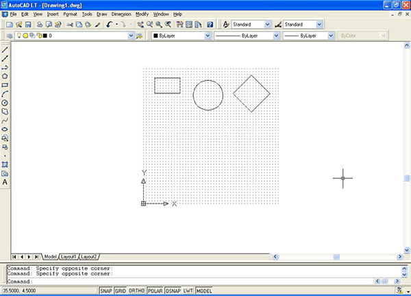
When printing from AutoCAD you will need to set up your AutoCAD page so that it is square. . A square page in AutoCAD prevents the objects from rotating 90 degrees when you print them. The page in the example below is set to 24 x 24 inches.
1. Place all of your objects in the upper portion of the AutoCAD page (see illustration below). If you have a 24 x 24 inch page and you are printing to a bed size of 24 x 12 inches (610 x 305 mm), the objects in the lower 12 inches will not be processed.
2. Set the Piece Size to match your AutoCAD page size.
Make sure to set the Piece Size in the Dashboard so is matches your AutoCAD page size. Setting both your AutoCAD page and the Dashboard print driver Piece Size to a square configuration (24” x 24”, for instance) is necessary to overcome AutoCAD’s tendency to rotate your artwork 90 degrees.

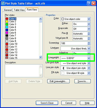
In the AutoCAD print window, set the pen colors that you are using to .001 inch.
The AutoCAD default for all pens is .010 and a line weight this large disables vector cutting.
If the line weight is not changed to .001 inch, vector cutting will not be possible.
When the laser receives a job where the line weights are too large, the laser system will just beep when you attempt to run the job.

Additional Helpful Hints
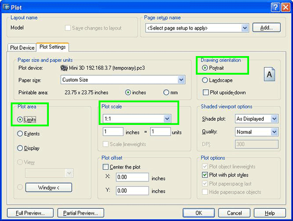
Use these settings in the AutoCAD print window:
Set the page orientation to Portrait.
Set Plot area to Limits.
Scale set to 1:1.
